The receive routine
The receive routine is based on two states: either looking for a device or sampling data from a found device.
There is also a timeout in case a sensors is not transmitting.
void read_port(unsigned char item){
unsigned char p = 0xFF;
long delay;
unsigned char a;
char b=0;
unsigned char d = 0 ;
unsigned char search = 0x17;
int e;
int t = 0;
BCSCTL1 |= RSEL3 | RSEL2 | RSEL1 | RSEL0; // increase speed
P1DIR = 0xF4; // Set P1.2 to output direction
P1OUT = 0xF8; // set p1.2 low to leave snooze mode set p1.3 high to mark sample point
TACTL = 0x1E4; // start timer ACLK /8 continuous mode
for( e = 0; e < 5000 ; e++); // wait to awake from snoze
hit = 0; // reset hit marker
while(t < 1500 & hit == 0){
t = TAR;
d = 0;
p = 0x17;
while(p != 0){ // wait for startbit
p = P1IN;
p &= 0x02;
}
delay = 15;
while(delay > 1) // half bit extra delay at start
delay--;
for(a = 8; a > 0 ; a--){
delay = 33;
while(delay > 1)
delay--;
d = d >> 1;
P1OUT = 0xF8; // set sample pin
p = P1IN;
p &= 0x02;
p = p << 6; // LSB first
d |= p;
} // one byte ready
//send_char(d);
//BCSCTL1 |= RSEL3 | RSEL2 | RSEL1 | RSEL0; // increase speed
if((search == 0x17) & (d == (0x41 + item ))){
search = 0x16;
}
else if(search == 0x16){
buffer[b++] = d;
if( b > size[item])
hit = 0x17;
} // end of char
delay = 15;
while(delay > 1) // half bit extra delay at end
delay--;
} // end of timeout
BCSCTL1 = RSEL2 | RSEL1 | RSEL0; // reduce speed
P1OUT = 0xF4; // set P1.2 high to enter snooze mode
}
The love of a box
This solution will be very thight, but I have some faith in proceeding the project.
Does it fit?

Making heavy progress
Now comes the ethical part if it is ok not to centre the button around the otterbox membrane.
I will probably take the decision myself without going into deep discussion with my girlfriend which at the moment is studying art-history.
uncentred button

PCB version 0.1
I have not tested the reception from the Xbee module but that part "should" not cause any problems since it was working last year.
I need to get my etching things together and make some kind of fine art-work.
Perhaps I will try to place the components in a way to make the unit float in proper balance.
The box

Chosing colours
The green bars are a bit to vague in contrast to the background maybe I have to change colour.
But I am happy with the lowest row showing voltage as current, max and min values.
Display output version 0.1

The stack problem
When calling the same subroutine the compiler tries to save time and space by wating
to adjust the stack pointer.
In my case this will probably not be a problem since I need to insert some delay between the calls to the display (I don't take care of the ACK sent from the display).
Problems with the compiler
When I run the debugger the stack is never adjusted after a return ending up in a stack overflow.
I probably missed some settings in the options for the compiler, but temporarely I solved it by
using global variables for the two last arguments (a little dirty perhaps).
Some simpel ways for the sensors transmit routine
Each sensor is identified by a capital letter ie. "A" is data from the solar panel "B" is from the generator.
Send routine for the sensors
void send_package(void){
int i;
int d;
P1DIR |= 0x0C; // Set P1.2 & 3 to output direction
P1OUT &= 0x03; // set P1.3 low to mark start of no snooze
for( d = 0; d < 500 ; d++);
P1OUT |= 0x08; // set P1.3 high to mark start transmission
send_char('A'); // identify the solar panel by an A
make_string(sample_scaled); // format and send current amps
for(i = 0x01; i < 3 ; i++)
send_char(st[i]);
make_string(sample_max); // format and send max
for(i = 0x01; i < 3 ; i++)
send_char(st[i]);
make_string(amp_hour); // format and send last hours amps
for(i = 0x0; i < 3 ; i++)
send_char(st[i]);
make_string(amp_per_day); // format and send last 24 hours amps
for(i = 0x0; i < 3 ; i++)
send_char(st[i]);
P1OUT |= 0x04; // set P1.2 high
seconds = seconds + 1;
if(seconds >=60){
seconds = 0;
minutes++;
if (minutes >= 60){
minutes = 0;
hours++;
calculate_amp_hour();
if(hours>=24)
hours = 0;
}
}
}
void send_char(char p_i){
int p,i,j;
P1OUT |= 0x02;
BCSCTL1 |= RSEL3 | RSEL2 | RSEL1 | RSEL0; // increase speed
P1DIR |= 0x02; // Set P1.1 to output direction
p = (int) p_i;
p = p << 1;
p |= 0x200; // add start and stop bit
for(i = 0; i < 10 ;i++){
for(j = 0; j < SERIAL_DELAY_9600; j++);
if((p & 0x01) != 0)
P1OUT = 0x02; // set bit high
else
P1OUT = 0x00; // set bit low
p = p >> 1;
}
P1OUT |= 0x02;
for(j = 0; j < SERIAL_DELAY; j++);
BCSCTL1 = RSEL2 | RSEL1 | RSEL0; // reduce speed
}
void calculate_amp_hour(void){
int i;
amp_hour = sum / amp_divider;
sum = 0;
sample_max = sample_scaled;
for(i = 23 ; i >= 0 ; i--){
amp_history[i] = amp_history[i-1]; // rotate last 23 hours
}
amp_history[0] = amp_hour; // insert latest hour
amp_per_day = 0;
for(i = 23 ; i >= 0 ; i--){
amp_per_day += amp_history[i];
}
}
Making breadboards
I like to try and keep the connections down to a reasonable small amount.
Sometimes I run the breaboards a full season withot making any PCB.
Since the frequencies are quit low it usually runs ok without any large groud plate.
For this design I probably will try to make a PCB to get it to fit better in the box.
breadboard

Working out the user interface
But perhaps I will be happy with the solution allthough most people would not understand imediately.
Green vs Red

Software for the initial measurement
After the conversion is finished the result is scaled to acomplish the 1bit/100mA approach. The scaled sample is added to a sum for later calculation of the amp hours, there is also a value saved to show the max current.
void ad_3(void){
int status = 0;
int i; CCTL0 = OUT; // TXD Idle as Mark
TACTL = TASSEL_1 + MC_2; // ACLK, Continuous mode
BCSCTL2 |= DIVS_3; // SMCLK/8
SD16CTL = SD16REFON + SD16SSEL_1; // Use 1.2V ref,
SMCLK SD16CCTL0 = SD16DF; // twos complement
SD16INCTL0 = SD16INCH_2; // SD16 A2+/- pin 6 & 7
SD16AE = SD16AE4 + SD16AE5; // A2+ and A2-
for(i=0; i<3600; i++);
SD16CCTL0 |= SD16SNGL; // Single conversion
SD16CCTL0 |= SD16SC; // Start conversion
while((status & SD16IFG) == 0)
status = SD16CCTL0; // Wait until ready
sampleData = SD16MEM0; // Read the sample
if(sampleData < 0)
sampleData = -sampleData;
SD16CTL = 0; // set reference off
SD16AE = 0; // disable inputs
scale();
sum_sample();
if(sample_scaled > sample_max)
sample_max = sample_scaled;
}
void scale(void){
unsigned int sample;
sample = sampleData;
sample = sample * scale_mult; // be careful to multiply first not to lose small values
sample = sample / scale_div;
sample_scaled = sample;
}
void sum_sample(void){
sum += sample_scaled;
}
Oled up and running
Some progress

TI tiny emulator
Once the code is loaded you can set two hardware breakpoints, stepping throgh code and scrutinizing variables is very easy. Ocassionally you need to reload the drivers, I have not found out why.The interface to the board is called spybiwire and takes up two wires instead of JTAGs normally four or five wires. In that way you can acess all 8 I/O ports while debugging.
The small emulator

Xbee as a cable replacement
Zigbee module

Don't use the P1REN register
monday "stimmung" picture

What is the goal for the "thing"
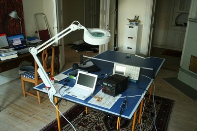
The smell of soldering
The CPU part

Software environment

IAR is working ok
Tools to make this small project get forward
The working environment